Overclocking computer components has traditionally been a delicate balance of power, thermals, voltage, and clock speed.
The tradeoff
The higher the clock speed, the more operations your processor can complete within a given period of time. However, it takes a minimum amount of time for the logic in your processor to be driven to a given logic level. If your clock speed is too fast, you’ll start violating timing requirements and cause instability. Increasing voltage reduces the amount of time it takes to settle to a given logic level, subsequently increasing your maximum theoretical clock speed. Unfortunately, it also increases power consumption. The cost of electricity aside, the components on your board are only capable of delivering power up to their specified limits. Before you reach that limit though, the increase in power consumption forces you to mind your thermals. Not only to avoid exceeding their maximum rated temperature, but also since silicon performs worse at higher temperatures.
To make things worse, your processor dynamically scales its clock speed based on load. This is especially important on battery power since hurtling along at maximum clock speed is a waste of energy at idle. Reducing clock speed lets us achieve the same result with less voltage, and thus less power. This means, for every single clock speed our processor could be at, we need to ensure:
- The voltage is sufficient such that logic levels settle fast enough
- The voltage is low enough such that it doesn’t use too much power
- The power is low enough such that the processor (and any power delivery) doesn’t get too hot
- Some other details I’ll leave out (voltage is low enough such that electro-migration doesn’t happen, some considerations related to the process node etc.)
Of course, there are clock speeds our processor won’t be able to achieve since at least one of the conditions will be violated. For example, there will most certainly be a frequency where the voltage you’d need to drive the processor at to achieve it would cause it to overheat or incur damage.
Something I glossed over is cooling, which is what buys the thermal headroom in the first place. If your components are air-cooled, you’ll also need to make a trade-off between fan speed, cooling performance, and noise. I could write an entire article about cooling, so I’ll leave it at that.
We need to go faster
Modern processors are capable of on-demand boosting, which allows them to temporarily increase their clock speeds past their base specification depending on load. Many workflows tend to be bursty in nature, such as browsing the web. Boosting allows us to adapt to bursty workloads by temporarily increasing clock speeds, improving perceivable latency amongst other things. Sometimes you could make the argument that completing work faster allows the processor to return to an idle state quicker.
Why not stay at boost clocks indefinitely? We are abusing the fact that the processor takes time to heat up due to thermal mass, so it’s possible to achieve higher than normal clocks for a short period of time. There is no equilibrium though - eventually the processor will get too hot to continue running at boost frequencies, at which point it needs to decide between lowering its frequency or returning to sand.
Precision Boost Overdrive
The latest Ryzen processors from AMD have a feature named Precision Boost (and Precision Boost 2), which balances several of the factors I mentioned above to scale clock speeds on a per-core basis. If you’re interested in the details, consider looking it up because how Precision Boost works has been covered to death.
Precision Boost Overdrive (PBO) is a feature which allows you to overclock your processor by tweaking the parameters used by Precision Boost. This differs from traditional overclocking in which we typically set either the maximum boost or base frequency to a fixed value, then tune voltage to an appropriate fixed value or auto-offset. While this might be easier, we are leaving a lot on the table for reasons I’ll briefly go over later. Here are the knobs and dials which PBO gives us to tune the behavior of Precision Boost:
Limits
- Package Power Tracking (PPT)
- The maximum power that can be delivered to the CPU socket, in watts.
- Thermal Design Current (TDC)
- The maximum current that can be delivered in sustained loads, when constrained by thermals, in amps.
- Electrical Design Current (EDC)
- The maximum current that can be delivered in transient loads, when constrained by electrical characteristics, in amps.
PBO allows us to tweak the power and current limits applied to the CPU on a global basis. Raising power limits allows cores to operate on higher clock speeds by indirectly giving them more budget to be driven at higher voltages. Of course, there’s a limit to how high we can push them, which is thermals again. Not only of the CPU, but also the regulators and other components on the motherboard.
Curve Optimizer
- Voltage-Frequency Curve
- A relation which specifies the minimum voltage required to drive the processor at a given frequency.
Curve optimizer allows us to apply an offset to the voltage-frequency curve. This is similar to undervolting by applying a negative auto-offset, except curve optimizer allows us to do it on a per-core basis. This is important because even though they are on the same die, you will see that some cores require less voltage to run at a certain frequency. By achieving the same frequency but with less voltage, we unlock thermal headroom which allows us to remain at higher frequencies for a longer period of time.
The downside is that it is notoriously difficult to ensure your configuration is stable. With traditional overclocking, you could be fairly confident that your overclock is stable by just running a torture test, since the voltage is fixed at a point which should be sufficient for any frequency the CPU could possibly encounter. This means that the maximum frequency is where we would most likely see instability. Of course, this means our voltages are unnecessarily high for lower frequencies, costing us precious thermal headroom and power consumption. The situation is a bit better with auto-offset voltages, but the offset is constrained by the worst core on the processor and terrible implementations by motherboard vendors.
Since we are applying the offset to a curve, we effectively have to test every frequency on every core in order to ensure system stability.
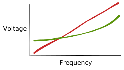 For example, if the green line represents the minimum voltage required at a given
frequency for the core to be stable, and the red line is the current
voltage-frequency curve, we would see instability at lower frequencies (i.e.
when the core is idle!)
For example, if the green line represents the minimum voltage required at a given
frequency for the core to be stable, and the red line is the current
voltage-frequency curve, we would see instability at lower frequencies (i.e.
when the core is idle!)
We can’t move the green line since it is a physical property of the core, but we can move the red line around using curve optimizer by applying a voltage offset.
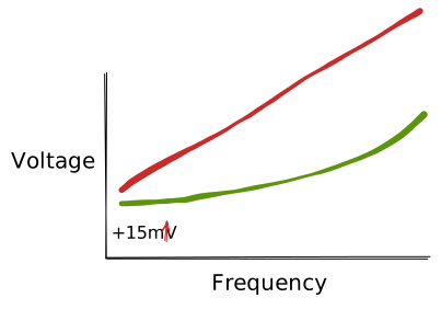
Fifteen millivolts is enough to clear the green line everywhere, at the cost of exactly the headroom we were trying to win. The interesting direction is the other one: push the red line down as far as it will go without crossing the green line at any frequency, on any core.
There exist tools such as CoreCycler which helps exercise different parts of the voltage-frequency curve on a per-core basis, to help with verifying stability. After a bunch of tedious work, we can arrive at a set of core offsets which will generally reduce the amount of power our CPU consumes, giving it more headroom.
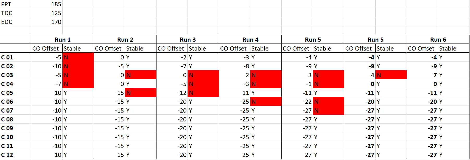
It’s worth mentioning that CoreCycler creates synthetic conditions which aren’t realistic, which is why you’ll sometimes see instability with CoreCycler but no issues under normal use. Sometimes you’ll even need to apply positive offsets, which implies that the processor was unstable out of the box!
Scalar
- Scalar Multiplier
- How much silicon wear the boost algorithm is allowed to accept when it decides how long to hold a high voltage, from 1X to 10X.
Precision Boost carries an internal model of how fast the silicon wears out. Time at high voltage wears it faster than time at low voltage, and the algorithm keeps the total over the part’s expected life to something it considers safe. Scalar tells it to allow more: at 10X, AMD’s framing is that you’re accepting roughly ten times the degradation rate you’d otherwise see.
So what does it actually buy? Time. The core sits nearer the top of the curve for longer before the algorithm pulls it back. It doesn’t raise the ceiling, and it won’t make a core stable at a voltage that wasn’t stable before. It buys that time by holding voltage higher, which costs the same thermal headroom that was pulling the core down in the first place. On air, that mostly cancels out. I left it at 1X, though I’ve never seen the degradation claim measured by anyone outside AMD, and I don’t know how you’d measure it in under a decade.
Auto OC
- Maximum Boost Offset
- An offset applied to the maximum boost frequency the processor can achieve globally, in 25 MHz steps, up to +200 MHz.
This is the one knob in PBO that behaves like traditional overclocking: it raises a number, and the number is a ceiling. It’s also the knob that does the least, because a ceiling only matters if we were touching it. Under an all-core load we never are. PPT or thermals run out long before frequency does. It shows up in one- and two-thread work, where a single core has the whole power and thermal budget to itself, which is conveniently most of what a desktop does.
The catch is that raising the ceiling doesn’t grant us the voltage to reach it. The curve still says what it says, and the new top of it wants more voltage than the old top did. That’s why curve optimizer and maximum boost offset are recommended together and rarely alone: the offset asks for frequency we have no headroom for, and curve optimizer is what produces the headroom.
Thermal Limit
- Maximum Temperature
- The die temperature the boost algorithm targets, measured from a network of sensors spread across the die and reported as the hottest of them.
The name suggests a safety valve. It is really a target: the algorithm raises clocks until it runs into a limit, and on a decent cooler with the power limits already raised, the limit it runs into is this one. A chip sitting at 90C under sustained load isn’t in distress. Buy a better cooler and it won’t run any cooler. It will run faster at the same temperature.
Which means the knob only works in one direction. We can’t set it above the part’s TjMax (90C on the 5900X and 5950X, 95C on the 5600X and 5800X), but we can set it lower. Cap it at something like 75C and we spend less time at high clocks, but the fans never have to ramp. Mind that the reported number is a maximum over a sensor network, sampled quickly, so it spikes. Key a fan curve straight off it and you get a fan that screams every time a background task wakes up.
Was it worth it?
The screenshot above is six rounds of CoreCycler across twelve cores at 185 W PPT, 125 A TDC and 170 A EDC, and it took most of a weekend: a few hours of the machine being unusable, then a crash or a clean pass, then one number changed and around again.
The cores converged unevenly. Six settled at -27, the rest at -20, -11, -9, -4, 0 and +7. The low-numbered cores are the ones AMD’s ordering marks as the best of the batch, which makes them the cores a single-threaded load lands on, and also the ones that tolerate the least undervolt. The fast cores are the fragile cores.
And then there’s core 3, which needed +7. A positive offset: that core couldn’t hold its own stock curve out of the box, and had been quietly returning wrong answers for however long I’d owned it. Nothing had visibly crashed.
I never benchmarked this properly before and after, so I can’t put a number on what the tuning bought. Probably single digits in the things that respond at all. Core 3 was unstable at stock, and isn’t now.